How Can We Help?
mRo Quad Zero Kit
This guide is obsolete. Please visit our new docs site for the update assembly guide.
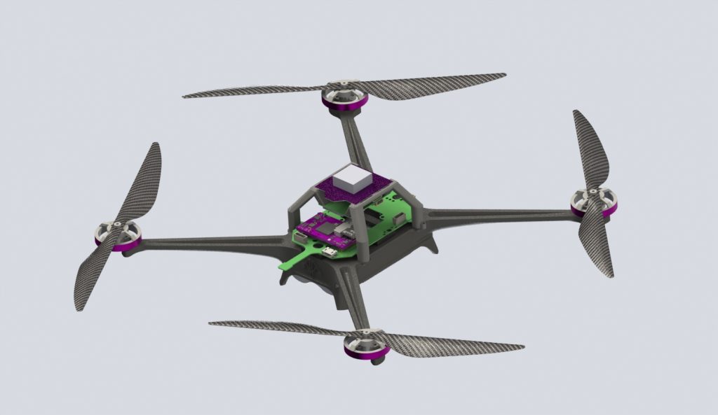
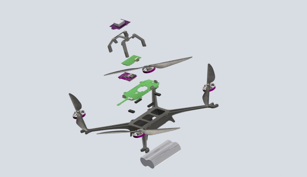
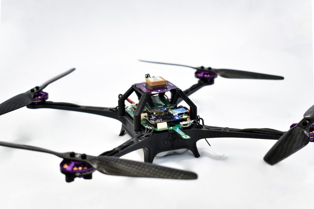
The mRo Quad Zero drone is a sub-250g focused on ultralight payloads and extended flight times (1hr). This kit is perfect as a development platform, educational, or even a light show drone – light and FPV pod coming soon!
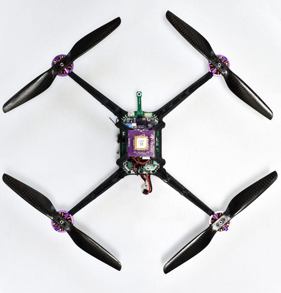
We provide a complete build log for Ardupilot and PX4 for beginners and experienced builders. We developed a telemetry radio around this drone to enhance its “developer platform” character, as it provides the hardware to include external sensors and send information over custom MAVLink messages or, on the contrary, use those messages to push commands to any actuator without disrupting the flight stack or the autopilot’s pinout.
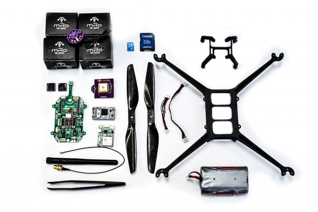
What's inside?
1x – QZ Frame
1x – GPS Mount
1x – QZ Carrier Board
1x – mRo SAM GPS + IST8308 Mag (Med Size) MRO10038
1x – Dual Band WiFi Telemetry (optional)
1x – Battery Pack (2s Lio-Ion 4200 mAh)
1x – FrSky R-XSR Rx
1x – SD card (included with OEM H7)
1x – Damping foams and cables
What else you'll need?
– Radio Transmitter control system compatible with FrSky .
– Laptop or tablet running any ground control station software.
Extra tools:
– Small flat screwdriver.
– M1.5 Allen key.
– Soldering Iron
– 3M VHB (or any double sided tape).
OPTIONAL
– Super X glue (to fix motor cables to the frame).
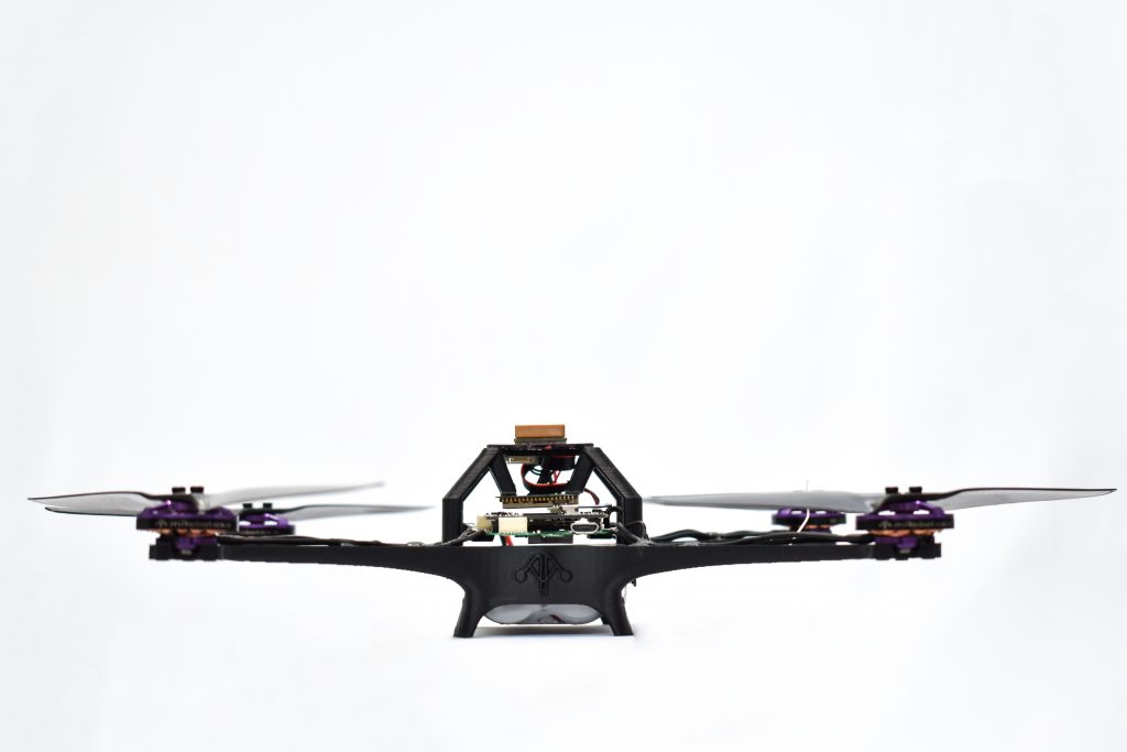
Assembling the airframe
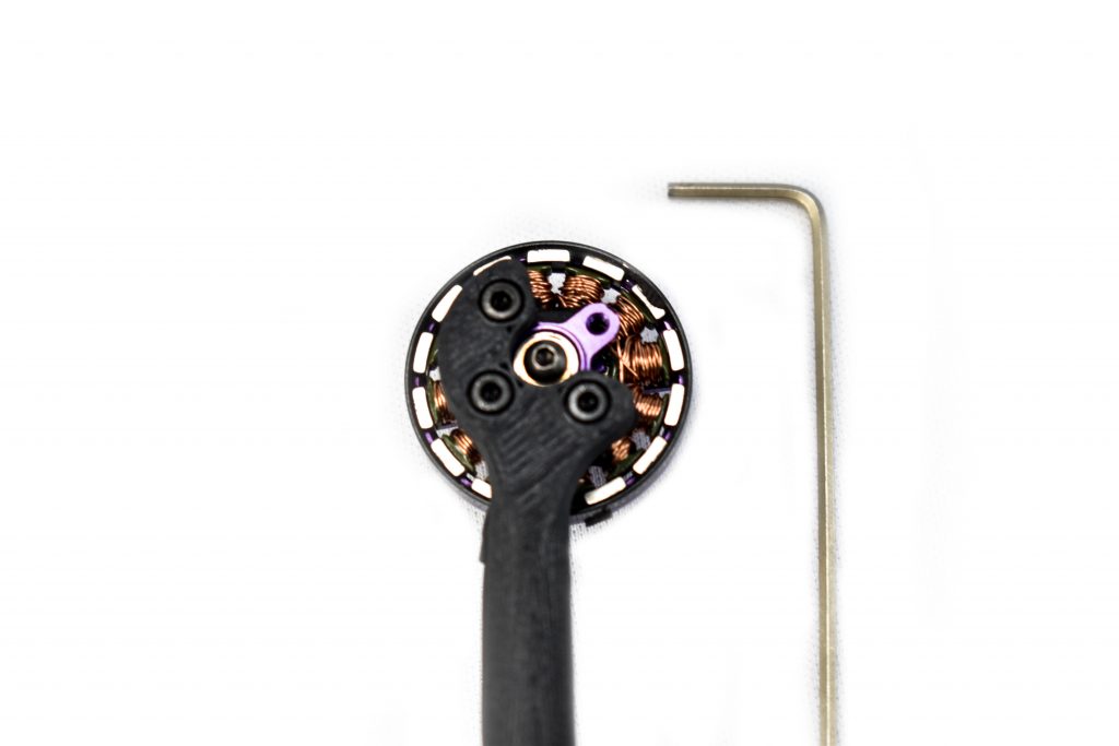
Screw the four mRo MI – 2202 motors to the Quad Zero frame using the M1.5 Allen key and the shorter screws inside each motor box.
RX reciever
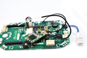
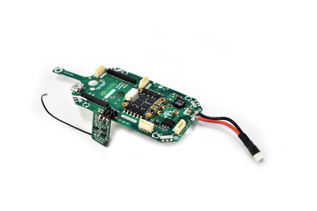
Tip: We recommend to solder the RX receiver before placing the Carrier Board on the Quad Zero frame.
You can mount your receiver however you like. There are two examples on the images above: on the left, the RX receiver is placed on top of the OEM Carrier Board; on the right, it is placed on one side of the Carrier Board.
Important: consider that the pinout (RC_IN / RC_V_SEL / GND) on the OEM Carrier Board matches the FrSky R-XSR pinout (SBUS / +5V / GND).
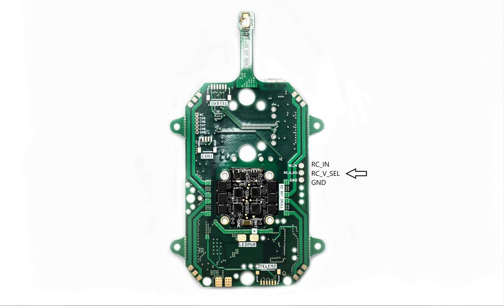
Note: This is the bottom face of the Carrier Board.
Damping foams
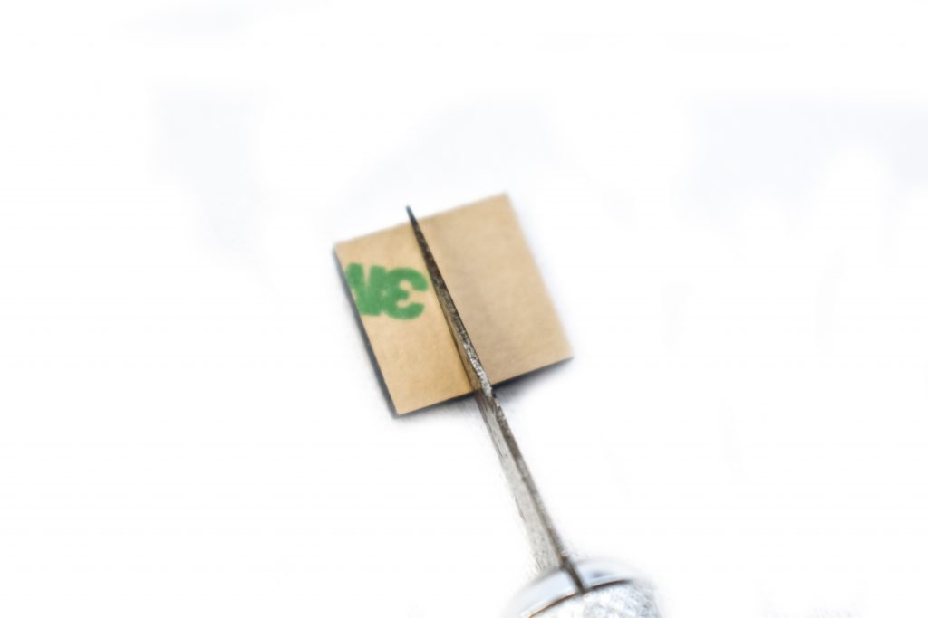
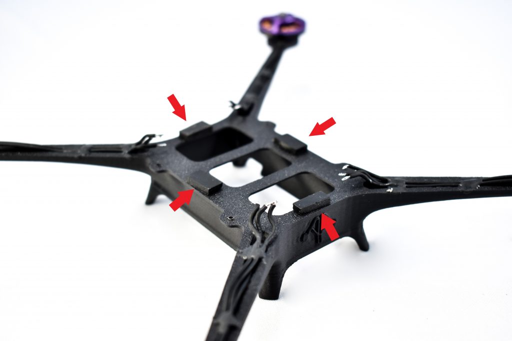
Your next step is to cut each damping foam into two equal parts; you can use any cutting tool, like an X-Acto. Each damping foam piece needs to be sticked as shown in the right image above, they will help the IMUs perform better during flight. A drop of CA glue is recommended to bond permanently the damping material to the frame.
Carrier board and soldering the motors
You may now place the Carrier Board on the damping foams; but make sure it’s centered on the frame.
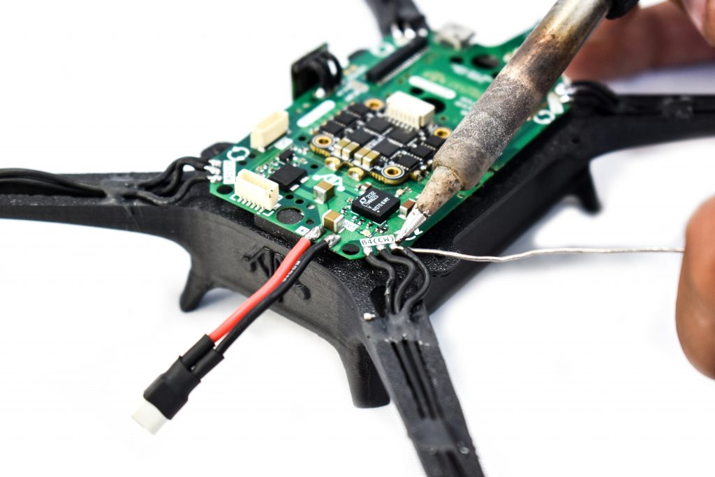
Solder all motor wires to the OEM Carrier Board. The order of the connection doesn’t matter, as you can change it later on. In the Bench Test section you will test motors rotation to ensure all are correctly set.
Important: If you are going to use PX4 firmware version 1.12.x or earlier, you need to swap wires of CH1 and CH3 in one of the connectors of the ST-SH 6 to JST-SH 6 cable .
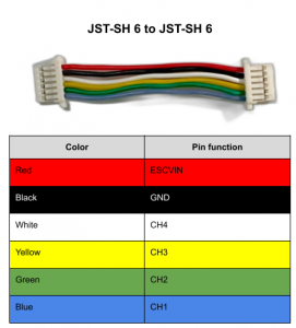
Then connect the JST-SH 6 to JST-SH 6 cable to the ESC and to the PWMESC connector on the Carrier Board.
Mounting the flight controller
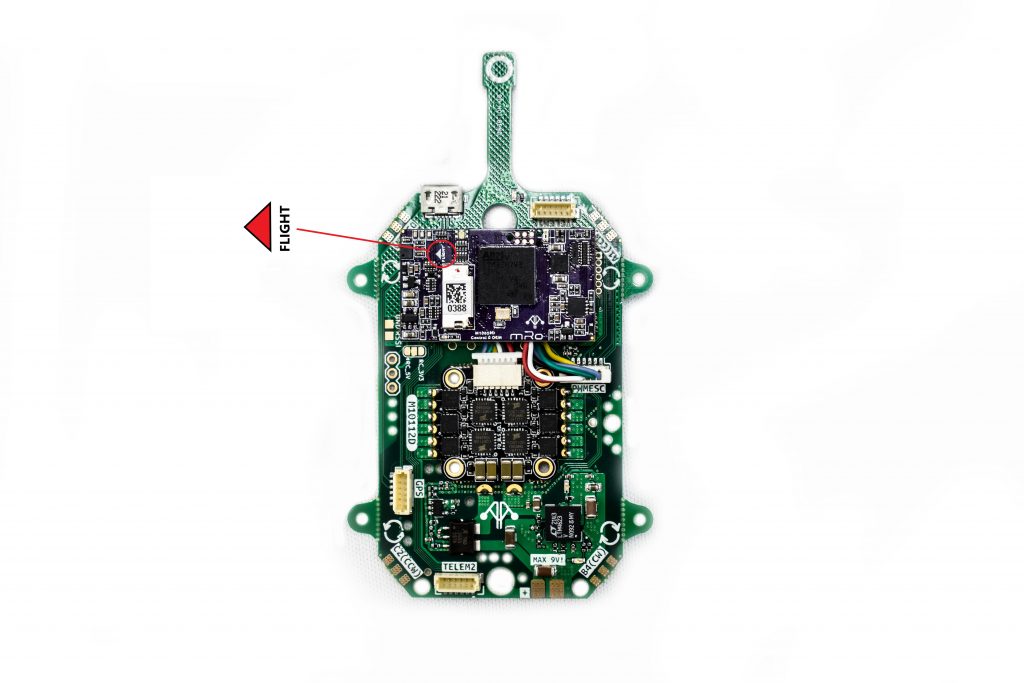
Next, insert the mRo Control Zero OEM H7 on the Carrier board with its flight direction sign pointing to the left. NOTE: If the CZ is placed backwards, the pins or the board’s components may be damaged, pinout is asymmetrical so there is only one way to place the flight controller.
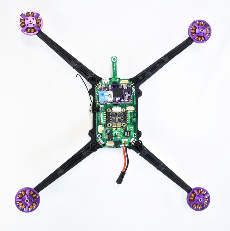
This result should be obtained once the carrier board is mounted on the frame, the motors are soldered, and the CZ is inserted into the carrier board.
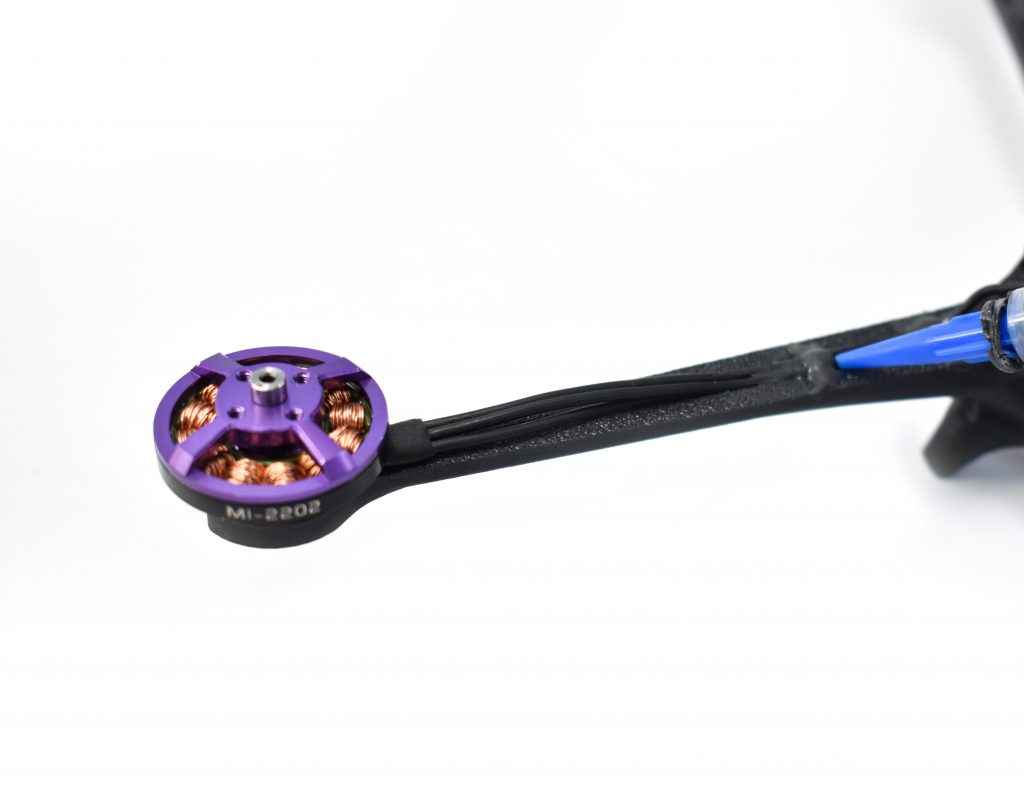
Recommendation: Use Super X glue to fix the motor cables to the frame to reduce vibrations and prevent tangling the motor’s cables in-flight. Heat-shrink tubing or other silicones may be used.
GPS mount
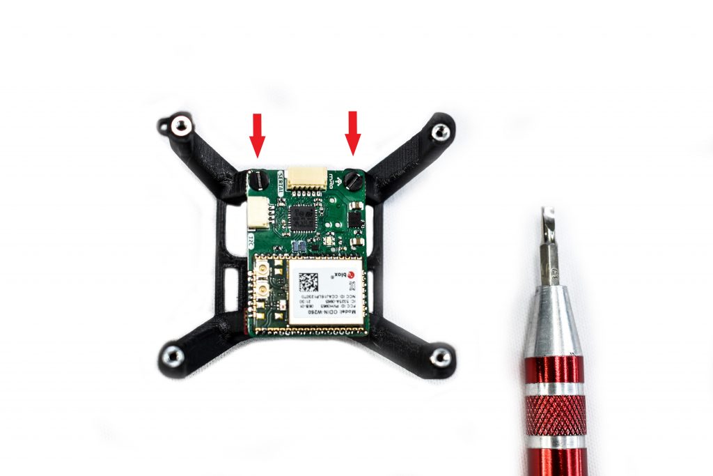
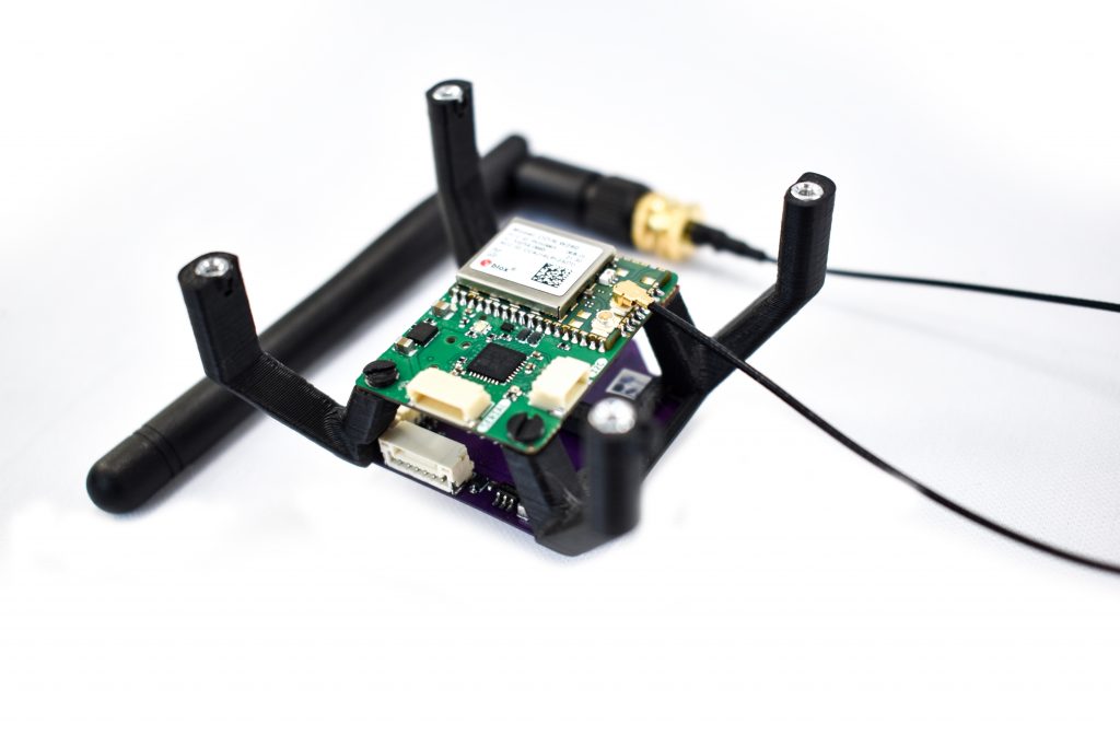
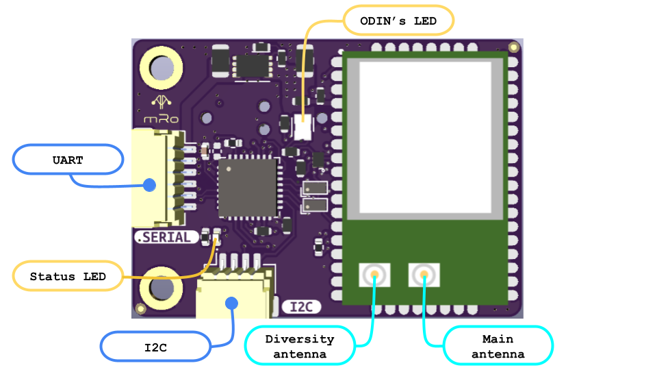
With the help of a small flat screwdriver and two 2-56 Nylon screws, screw the mRo DualBand Wi-Fi Telemetry Radio to the GPS mount as shown in the picture above. Then connect the antenna to the main antenna port.
To mount the mRo SAM GPS, cut four equal square pieces of 3M VHB, or any double-sided tape, and place them on each corner on top of the GPS mount. Then attach the GPS by exerting a little force towards the GPS mount.
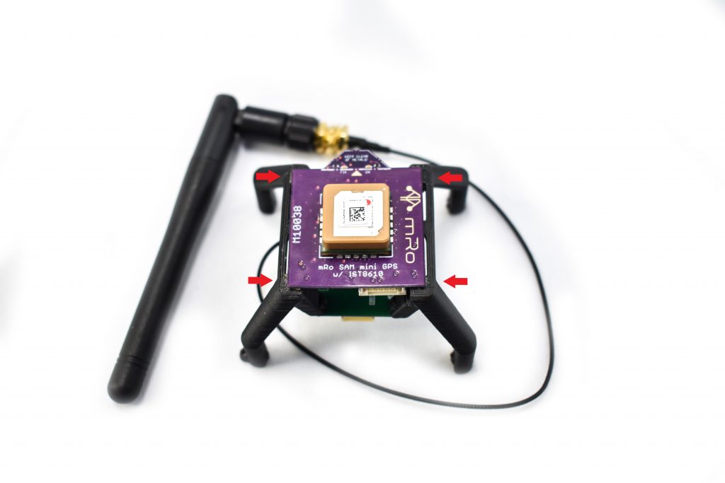
Note: make sure that the double sided tape sticks correctly to the GPS unit, if oil residues are present in the board from handling please us isoprpyl alcohol to clean everyhting before placing the board.
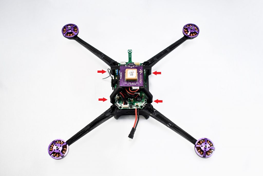
Using a small flat head screwdriver and four 2-56 nylon screws, screw the GPS mount to the QuadZero frame. The red arrows in the image on the left show where the holes are located.
Important: the GPS orientation indicator label needs to be pointing to the ToF sensor of the Carrier Board, as shown in the image.
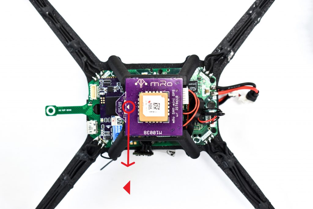
Then stick the Wi-Fi antenna to one side of the frame.
Wires connection
Use a cable to connect the SERIAL port located on the mRo DualBand Wi-Fi Telemetry Radio to the TELEM2 port of the Carrier Board.
Similarly, use a cable to connect the UART port on the mRo SAM GPS to the GPS port of the Carrier Board.
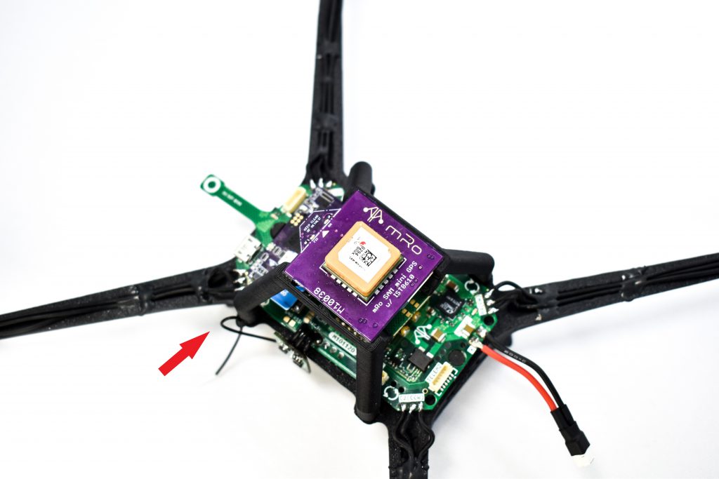
The feature indicated by the arrow is a hole that helps to place one of the Frsky antennas. The other antenna should be placed perpendicular to the first one.
Powering Quad Zero
Insert the battery in the compartment below the Quad Zero frame, making sure that the power cables of the battery and carrier board are on the same side.
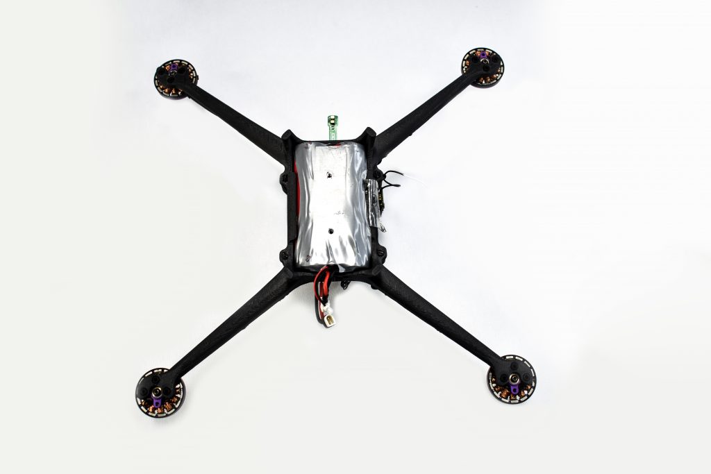
Now, you’re ready to power the Quad Zero and start the configuration setup using the USB port on the QZ Carrier Board.
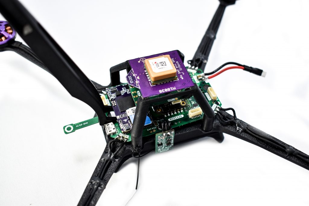
Note: If you want to remove the mRo Control Zero OEM, you must use the plastic tweezers tool to avoid any damage. Place the tweezers tip between the CZ and the Carrier Board and apply a little downward force. Do the same on the other side. Repeat this process three of four times until the CZ is completely out. Do not try to remove the CZ in one shot because you will damage the pins.
However, it’s recommended to prevent the removal of the Control Zero if it’s already attached to the Carrier Board.
Firmware Setup
For this section, you can choose which firmware you like best, Ardupilot or PX4! Use the USB connector on the Carrier board to connect the Quad Zero to your computer.
Using Ardupilot
First, load the Stable Arducopter Firmware, follow the steps in the following link (AC4.3.3+):
Note: Repeat the last step at least one more time to have all the parameters properly written. Use the ‘Compare Params’ feature to make sure all the parameters have been written correctly.
Using PX4
First, install the Stable PX4 Firmware; follow the steps in the following link:
- After that, download the following file “mRo_QuadZero.params“, next go to QGCS and click on the QGCS Logo on the top left corner > Vehicle Setup > Parameters > Tools > Load From File (Select the downloaded file) > Ok.
Wireless telemetry link
Once you have your Quad Zero powered on, wait for the Status LED on the mRo DualBand Wi-Fi Telemetry Radio to turn solid green, a Wi-Fi network will be created automatically.
Then connect your computer/tablet to the “mRo_wifi” network using “controlZero” as password.
Use the following configuration settings to establish communication with your GCS software:
Mission Planner
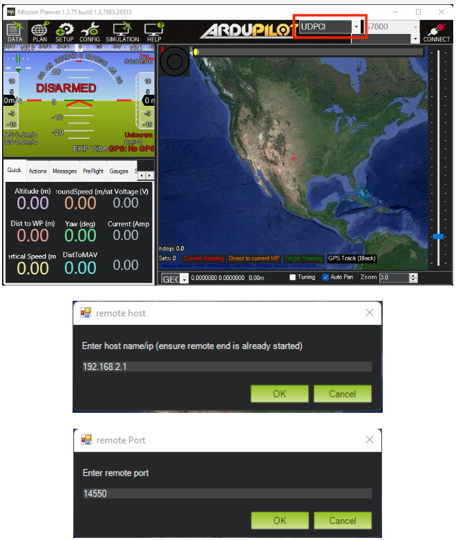
Select UDPCI as the connection type. Enter 192.168.2.1 when asked for the host name/ip, and 14550 as the remote port.
QGroundControl
Click on the Qground Logo on left top corner > Applications Settings > Comm Links > Add > Insert the following parameters:
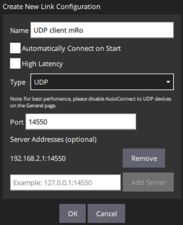
Click connect, and you’ll have a telemetry connection to the Quad Zero. For more options and details about the advanced configuration of the mRo DualBand Wi-Fi Telemetry Radio, visit:
mRo DualBand Wi-Fi Telemetry Radio
Motor Direction Test
Before starting the vehicle setup configuration, you’ll need to do a bench test to verify that the directions of all motors are correct.
Important: Make sure there are no propellers on your copter for this test!
Motor directions should match the following diagram:

Ardupilot. Quad X configuration [Diagram]. https://ardupilot.org/copter/_images/motororder-quad-x-2d.png
To do this test on Mission Planner go to: Setup > Optional Hardware > Motor Test
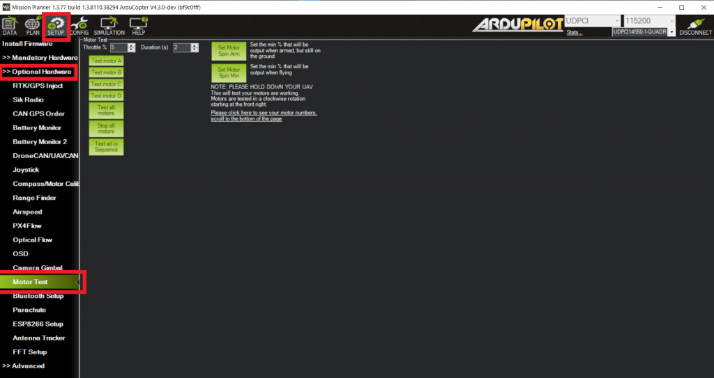
Click on each motor to verify it’s spinning in the right direction. If the motor direction is wrong, you can reverse the movement by swapping two of the three ESC to motor power leads; after that, check again the spin direction.
On QGroundControl, go to Vehicle Setup > Motors:
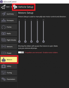
Enable motors movement by clicking on the switch below the bars. Each bar represents the throttle of each motor. Drag the controls upwards to spin the motors.
For more information about motor directions, you can follow the next link:
Vehicle Setup
After you have checked the direction of all motors, you can now place the propellers (with the battery disconnected). Make sure you insert the correct type in each motor (CW or CCW). If you have doubts about it, the following link can help you:
Note: This section is divided into Ardupilot and PX4 because each has a different vehicle setup method. Ardupilot Firmware will use Mission Planner, and PX4 Firmware will use the QGCS for the following configurations.
As part of the initial setup, you will need to configure and calibrate some necessary hardware components. The linked articles describe the process for setting up the compass and accelerometer:
To set up the RC transmitter/receiver, follow the next steps:
1. Put your Transmitter in Binding mode. Each TX has its method, follow the steps based on your model.
2. Connect the battery to the Carrier Board while holding the F/S button on the receiver. The LED on the receiver will flash, indicating the binding process is completed. Release the F/S button on the receiver.
3. Turn off both, the transmitter and the receiver.
4. Turn on the transmitter and connect the battery to the Carrier Board.
5. The green LED on the receiver indicates the RX is receiving commands from the transmitter.
If the receiver LED is red flashing, try to repeat the process. If the problem persists, check that you have the latest version of the ACCST D16 firmware on your transmitter. You can find the newest version of the firmware compatible with the receiver in the following link:
XM PLUS
If you have a multi-protocol transmitter and are having trouble connecting to the receiver, this link provides an easy way to download the latest firmware file for your MULTI module:
Finally, once you have bound your Transmitter with the RX, you will need to proceed with the radio calibration and flight modes setup:
After that, you’re READY TO TAKEOFF! Flight safe and enjoy.
Useful Links
– mro_QuadZero_Parameters(Ardupilot)
– mRo DualBand Wi-Fi Telemetry Radio
– Recognizing clockwise and counterclockwise propellers
– Compass Calibration (Ardupilot)
– Accelerometer Calibration (Ardupilot)
– XM PLUS
– Radio Control Calibration (Ardupilot)
– Flight Modes(Ardupilot)
– Install Stable PX4 Firmware (PX4)
– mRo_QuadZero.params (PX4)
– Compass Calibration (PX4)
– Accelerometer Calibration (PX4)
– Radio Control Setup (PX4)
– Flight Modes (PX4)
